Calculation of the reinforcement of an opening in a load-bearing wall. Calculation of a metal lintel for a load-bearing wall
The blank concrete wall shook from the powerful blows of the sledgehammer. The ominous echo melted between the eighth and ninth floors, and the torn brick quickly flew down. This is exactly how an opening in the wall will be created if the work is done incorrectly. If you are going to make some redevelopment in the apartment and think that breaking is not building, then you will have to forget about this simple saying. Just the opposite, both to break and to build...
Redevelopment and dismantling of load-bearing walls under the opening
It is impossible to carry out redevelopment in an apartment without additional work for dismantling walls. Dismantling of walls is carried out by cutting openings, so these works are considered complex, where it is necessary to take into account the properties and features load-bearing structures.
Everyone knows about the need to coordinate the creation of openings in load-bearing walls, especially meticulous neighbors in the house. The initial stage of expanding or dismantling an opening in load-bearing walls is the approval of the redevelopment project. Among the redevelopment activities, it is necessary to note the importance of the main stages:
design and approval
calculation of load-bearing structures of the opening
installation of reinforced metal structures.
These measures relate to the construction and dismantling of openings and inter-apartment partitions. In this case, information from the housing inspection is taken into account, confirming the information that these partitions are load-bearing.
Regulated redevelopment work will eliminate the occurrence of further problems, and technologically correct work will protect residents. How should the creation of openings be coordinated not only on paper?
First, let's define the concept of “opening in a load-bearing wall.”
Rules for arranging openings
As paradoxical as it may be to realize, the walls of modern houses are, in most cases, load-bearing. Openings in the walls are made to combine adjacent rooms or to connect adjacent apartments as inter-apartment partitions. However, the seemingly deadlock situation can be resolved.
There are the following regulations that regulate the rules for constructing openings in load-bearing walls:
SP 20.13330.2011. Loads and impacts
SP 52-101-2003 Concrete and reinforced concrete structures
SP 15.13330.2010 Stone and reinforced stone structures
SP 70.13330.2011 Load-bearing and enclosing structures
SP 54.13330.2011 Residential multi-apartment buildings.
According to regulatory building codes and rules, all information about the technical condition of the structure load-bearing wall and the possibility of creating or strengthening the opening must be reflected in the design. The subsequent fate of the opening will depend on the following factors:
the size of the created or existing opening
its possible location
coordination of opening dimensions and lintel material
a method of strengthening an opening with lintels and metal profiles.
Let us remind you that there are certain restrictions that do not allow us to coordinate the project for creating an opening. This is cutting an opening directly under the joints of interfloor slabs and load-bearing beams, violating the structural integrity of existing columns and pillars. The problem of strengthening an opening in a load-bearing wall is solved by installing lintels, which will literally “take” the entire weight of the load-bearing structure onto its shoulders.
There is a jumper!
Design and calculation of the lintel is considered the most critical stage of redevelopment. The safety of not only the “individual load-bearing wall” depends on the correct installation of the jumper. Take it cooler! On a global scale, or rather on the scale of a residential apartment building with grumpy neighbors. What needs to be taken into account and agreed upon when designing and calculating a lintel?
Of course, this is the following data:
opening area relative to wall area
distance from the opening to adjacent walls and ceilings
technical condition of the load-bearing wall and the material from which the wall is made
location and type of floor slabs
the number of floors above the wall and below the wall where the opening is made.
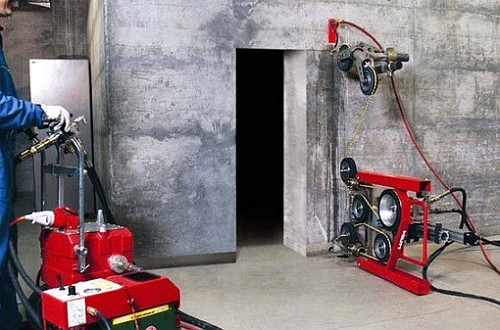
Let us recall that the load-bearing wall of a panel house is a monolithic structure made of fairly strong concrete. Therefore, it makes no sense to use an impact tool in the form of a sledgehammer, hammer drill or powerful jackhammer. Firstly, impact loads from the tool can damage the integrity of the wall, including damage to internal communications. Secondly, the work on cutting the opening in the inter-apartment partitions will move at a snail's pace. So why not take advantage modern methods diamond cutting?
How diamond cutting is performed to create an opening in a wall is presented in the video.
Considering the complexity of the work being carried out to create the opening, it is not recommended to risk cutting the opening with your own hands. Reasoned arguments suggest giving preference to specialists who have relevant work experience and SRO approval, as well as organizations that provide technical supervision of this type of work.
The result of cutting and strengthening a new opening will be considered an act indicating that hidden work has been carried out.
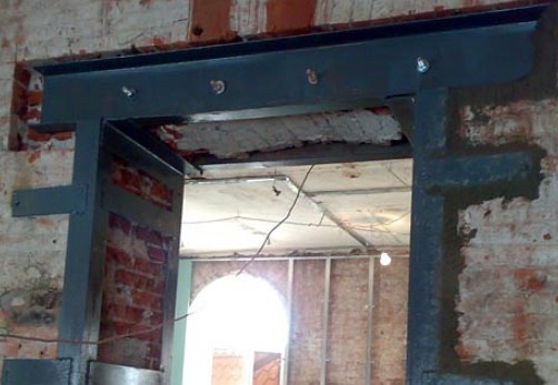
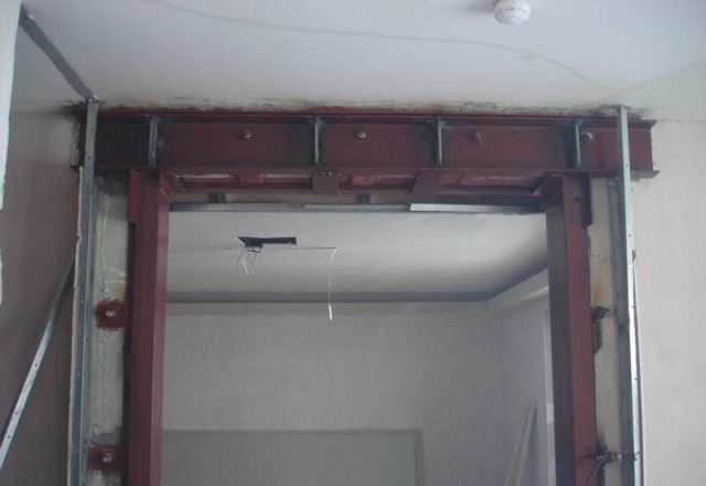
It is the high-quality installation of the jumper that will determine the safety of the structure. Therefore, the choice of lintel material can be considered of paramount importance. Preference is given to steel lintels, which consist of two channels, I-beams and angles.
"Iron" to create an opening
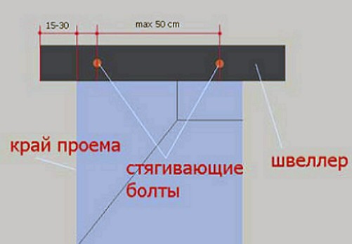
The design parameters of the hardware when creating an opening and installing a lintel will depend entirely on the length of the opening itself. The parameters must also be agreed upon. This must be remembered. As an example, for an opening 2.5 meters long, according to calculations, it is necessary to use channel No. 18, three meters long. The channel is fastened with coupling bolts.
Work practice suggests that preference should be given to bolts with a diameter of 20 mm and a length that will allow the channel to protrude from the wall side. The channels mounted in the prepared grooves are then cemented with M100 solution and installed by pressing. Then the coupling bolts are tightened and the channel is filled with cellular concrete.
Another example: to create an opening in a brick wall, the dimensions will be coordinated as follows:
We make calculations and outline the outline of the future opening on the wall
calculate and install a jumper made of two channels
we install and coordinate the location of vertical corners along the edges of the opening
We weld the corners to the top of the channel.
Thus, the approval of the arrangement of the opening in the wall will be carried out correctly and will not entail negative consequences or alterations.
More detailed information about creating an opening in a load-bearing wall is presented here.
Making a new or expanding an existing opening, especially in load-bearing walls, is carried out according to previously prepared calculation documentation. It clearly describes the entire sequence of work, starting with marking the opening and ending with its plastering, and also provides a specification of the material necessary for the work.
Main stages of work:
- development of project documentation;
- marking the opening;
- installation of temporary support posts;
- diamond cutting of the opening using special equipment;
- reinforcement of the opening with metal structures.
Redevelopment project for cutting and strengthening the opening, in mandatory must contain:
- Drawings of the opening and diagram of metal structures, detailing of sections, sections and assemblies.
- Statement of steel consumption (number of profiles, their sections, dimensions and weight).
- Conditions and sequence of work (what and how to do at the stage of preparation, dismantling, installation of reinforcement elements, caulking and plastering). The materials used, the tools used, etc., and the condition for submitting the finished work to the designer's supervision before finishing are specified.
All calculations and work must be performed by specialists from an organization that has SRO approval to carry out construction and installation work. You should not engage in project development and direct work on constructing and strengthening openings on your own, without having the appropriate knowledge and experience. Diamond cutting of an opening should be carried out only with professional equipment, since to ensure the structural integrity of the walls when constructing openings and disassembling partitions, the use of tools with high impact energy is prohibited.
The main reasons why it is necessary to calculate the gain:
- The wall is loaded - the floors above or the roof, if it is the top floor, rest on your wall.
- A fairly large part of the wall is cut through - dismantling even a small section of the wall weakens the partition.
- Assessment of the material from which the wall is made - for each type of material (monolith, brick, reinforced concrete panels) certain types of opening reinforcement are required. This will save you from installing amplification that may be insufficient for your conditions, or from installing excessive amplification, which means unnecessary financial costs.
It must be remembered that the implementation of openings and other work related to redevelopment, according to current legislation, is preceded by the preparation of the project and its approval by the relevant authorities.
These requirements should not be neglected. In the event that in the future you need to carry out any notarial actions with the apartment (sale, donation, etc.), the redevelopment will be declared illegal and a fine will be imposed on the owner.
Calculation of strengthening of openings
In the process of preparing a redevelopment project, engineering calculations are carried out. An important step here is the calculation of the reinforcement of openings, on the basis of which the corresponding section of the design documentation is developed. The design engineer, having received the data from the technical report on the possibility of redevelopment, makes the necessary calculations based on them, and, if necessary, goes to the site for additional measurements and research.
After processing all the information, the appropriate type of reinforcement is calculated, diagrams are drawn, recommendations are formulated on the order of work, the tools used, welding and fastening, as well as the inclusion of metal structures in the work (mortar installation, caulking, etc.).
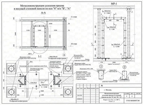
Opening reinforcement drawing
The graphic part of the section on cutting and strengthening the opening is detailed drawings along the axes with explanations:
- a view of the opening itself relative to its place in the wall, the upper and lower ceilings, the outer wall panel, heating risers, as well as indicating the main geometric dimensions.
- diagram of metal reinforcement with dimensions (general dimensions, spacing of fasteners). When depicting structures, a frontal view and a top view, as well as sections, are performed.
- all drawings are accompanied by footnotes, which can clarify additional parameters - dimensions and type of fasteners, sections and dimensions of metal profiles, etc.
- wall materials are indicated various types hatch lines.
- A detailed drawing of the metal reinforcement units is being completed.
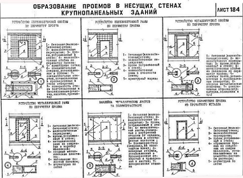
Strengthening the openings is necessary to preserve and increase the strength of the wall after partial dismantling. To strengthen the openings, special metal structures are used: corners, channels, etc., followed by embedding.
Types of strengthening load-bearing walls:
- single-row - standard strengthening of an opening in a concrete wall with a channel;
- corner - edging the opening with a corner;
- box, double-row with a stud tie - complex reinforcement of openings in a load-bearing wall, combining both of these types of reinforcement.
Reinforcing openings with channel bars
It is used for preliminary transfer of loads to the metal structure before cutting the opening and is characterized by high reliability and load-bearing capacity.
Installation of an H-shaped frame made of channel beams is carried out on both sides of the wall. The vertical frame posts are installed directly under the top floor. The frames are connected to each other with threaded rods. After installing the frame, an opening is cut in the load-bearing wall using diamond cutting.
The disadvantage of this reinforcement is that the frame structure is spaced from the wall at a distance equal to the width of the channel flange and requires further decoration.
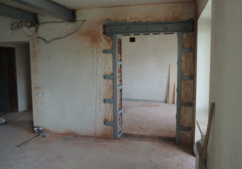
Strengthening openings with corners
Reinforcing openings with a corner is most often used when constructing new openings in panel houses. Depending on the thickness of the panel (14, 16, 18, 20, 22 cm), the floor on which the work is being carried out and the total number of storeys of the building, steel angles of different sizes are used, from the smallest 63x5mm to powerful angles 140x90x12mm. In all cases, the reinforcement of the opening consists of two corner frames on both sides of the wall, connected to each other by steel plates on all sides of the opening. Additional fastening elements can be mechanical anchor studs or reinforcement attached to chemical anchors.
Maximum reliability of this type of reinforcement is achieved due to the possibility of tapping seams between the steel frame and the wall during or after installation of the metal structure.
Combined gain
They are used in buildings where the wall thickness exceeds 300 mm. The horizontal part is reinforced with a channel, and the vertical posts are made from corners. Such structures are quite reliable and can maintain load-bearing capacity.
The disadvantage of this method of reinforcement is that the opening must be cut higher by an amount equal to the thickness of the channel, while the load-bearing capacity of this metal structure is maintained on the seams, which are made by welding. The welds are located in the corners and bear the entire main load. For this reason, everyone welding work here should only be carried out by highly qualified welders.
Complex strengthening of openings and walls is often carried out in Soviet and pre-Soviet buildings. Many buildings from this era have high ceilings and thick walls, and small doorways. Typically age as well as poor quality building materials used in construction require highest level safety of work at such facilities. Given these features, combined structures can take on a wide variety of designs.
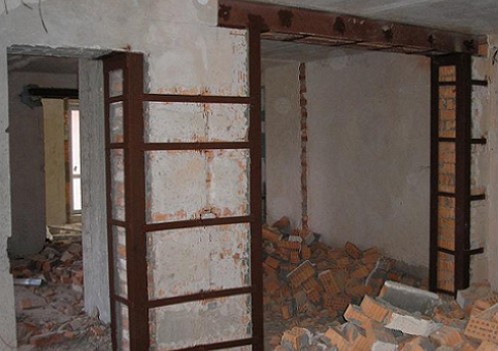
Strengthening openings in brick walls
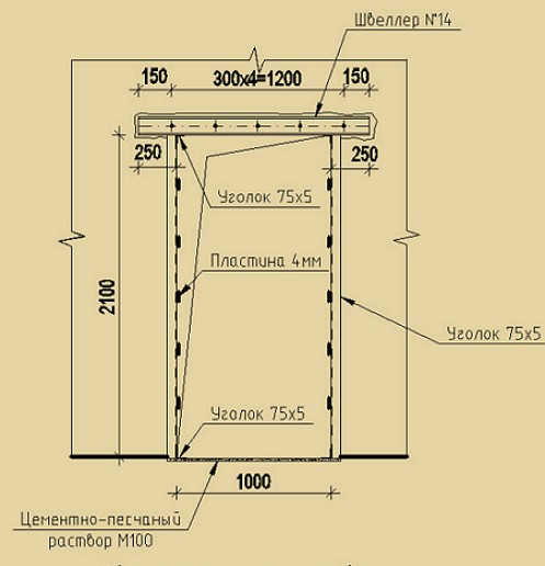
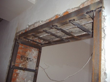
Openings in brick load-bearing walls are reinforced with a U-shaped metal frame made of corners or channels. Since brickwork does not have the solidity of reinforced concrete, openings in it should be made with caution. In brick walls, the upper lintel must be installed before dismantling the opening, and it is preferable to cut the opening with a diamond machine, otherwise the integrity of the brickwork can be damaged.
Immediately after the opening is dismantled, its vertical edges are reinforced with racks, which are attached to the wall with chemical anchor bolts or reinforcement, and to the horizontal lintel using welding. The corners, resting on the floor heels, serve as support for the lintel and at the same time strengthen the edges of the opening.
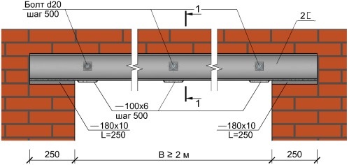
Openings in thick brick walls are often reinforced with a lintel made of two channels, tied together with studs and corner posts. Transverse metal strips connecting them are welded between the channels. The free spaces that appear between the profiles and the wall during installation are filled with mortar (caulked).
In old brickwork, it is often necessary to inject the voids between the bricks with a self-expanding polymer-cement mortar.
Strengthening openings in a concrete wall
The scheme and technology for strengthening the openings of concrete walls is the same as in brick ones. A U-shaped metal frame made of corners or channels is installed. In this case, reinforcement from corners is preferable, since it fits more tightly to the wall and is easier to caulk with mortar. Reinforcing structures are attached to the wall with chemical anchor bolts or reinforcement rods, and rest on metal heels, which are attached to the ceilings with reinforcement.
If the concrete wall is of considerable thickness, then the opening in it is reinforced with a structure with combined reinforcement - from the upper channel lintel and corners on the sides. The vertical supports of the angle profile are connected to the wall with anchor bolts, and the channels are connected to each other by welding strips and tie bolts through the wall.
There are also other non-standard reinforcement options, when it is necessary to take a side wall into a metal frame or, in addition to the main frame, to mount reinforcement for the floor.
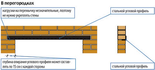
Strengthening the window opening
Unlike doorways in load-bearing walls that are reinforced with a U-shaped metal frame, for window openings an upper lintel made from corners or a channel is usually sufficient. At the same time, along the edges of the new window opening, on top, niches are cut out for installing reinforcement. In some cases, the reinforcement of the window opening is supplemented by side corners, which are connected to the lintel by welding, and to the walls - with bolts. It should be noted that cutting or widening window openings is also done using diamond cutting.
You should remember when choosing a contractor to install openings in load-bearing walls:
- Openings in load-bearing walls cannot be made without reinforcement;
- All openings must be cut with a professional diamond tool, without the use of perforators and jackhammers, regardless of the type and thickness of the wall;
- Temporary support posts must be installed for the entire duration of the work, under the above floors, to redistribute the loads;
- The metal structure must be in a stressed state.
- All seams between concrete and metal must be caulked with self-expanding mortar.
- Beams and racks of the structure must be wedged with metal wedges.
- The work usually takes 2 days (the first day is cutting, the second is welding work to strengthen). As a rule, it is almost impossible to perform high-quality work in one day.
To expand the scope of application of the above formulas, we additionally calculated the cross-section of a metal lintel for a brick load-bearing wall on which the floor slabs rest (the results are highlighted in red) or floor beams (results highlighted in blue).
1. Determination of loads per 1 linear meter of lintel:
1.1 From the weight of the masonry:
q 1 = p x b x h m/n,
Where,
p in kg/m3 - the density of the material from which the wall is laid, including masonry mortar and plaster. Density cement mortar on ordinary quartz sand - up to 2200, which theoretically needs to be taken into account when working with hollow bricks, gypsum blocks and lightweight concrete blocks, but in order not to bother with determining the proportion of mortar in the masonry, you can simply multiply the density of the material by 1.1 or take the maximum of below.
Note: Structural mechanics considers beams as rods, the height and width of which are not significant compared to the length. Therefore, when determining the distributed load from the weight of the masonry, we multiply the density of the brick by the height and width of the brickwork, obtaining a distributed load of 1 m/p, and if we also multiplied this distributed load by 1 meter of length, we would get the weight of 1 linear meter masonry
For reference:
Density of solid brick 1600 - 1900 kg/m3
- density of hollow bricks 1000 - 1450 kg/m3
- density of blocks made of foam concrete, aerated concrete, cellular concrete 300 - 1600 kg/m3
- density of gypsum blocks 900 - 1200 kg/m3
For example:
If the wall above the lintel is made of hollow bricks, then the value can be taken
p= 1500 kg/m³
- for gypsum blocks p= 1200 kg/m³
- for blocks made of lightweight concrete - depending on the density of the concrete. To determine this very density, you need to weigh 1 block (or try to approximately determine the weight of the block by simply lifting it), and then divide the weight by the height, width and thickness of the block. For example, if a block weighs 20 kg and has dimensions of 0.3x0.6x0.1 m, then the density of the block will be 20/(0.3x0.6x0.1) = 1111 kg/m3. In the same way, you can determine the density of the brick.
- in all other cases (especially if you do not know the density of the material and cannot determine its density) p= 1900 kg/m³
b- wall thickness in meters, for example for brick wall in two bricks should be taken = 0.51-0.55 m, for walls not finished with wet plaster - 0.51 m, for walls finished with wet plaster only indoors - 0.53 m, for walls finished with wet plaster and inside and outside - 0.55 m.
h- the height of the masonry above the lintel. Here questions may immediately arise: what if the height of the masonry above the lintel is 10 meters, does this entire height really need to be taken into account, what cross-section will the lintel have under such a load?
The answer to these questions will be as follows: any load is redistributed in such a way that only the load from the following section of the wall will actively act on the lintel:
those. For calculations, you can take the height h equal to half the length L jumpers. Of course, in in this case the distributed load will not be uniform, but will vary along the length of the jumper (in this case, you should use the appropriate calculation scheme to determine the maximum bending moment), but let’s not complicate what is already complex. If there is another opening above the design opening, then the height of the masonry in this case will be equal to the distance between the top of the lower opening and the bottom of the upper opening.
For an opening 1.5 m long for a brick wall 2 bricks thick, load
q 1 = 1900 x 0.53 x 0.5 x 1.5 = 755.3 kg/m
1.2. From the own weight of the metal jumper:
q 2 = n x P,
Where,
n- number of corners, channels or other profiles,
P- the own weight of 1 linear meter of an angle or channel, determined by the assortment, there is a small problem here, because how can you know the weight of a rolled profile if its cross-section is only determined, but as a rule, for metal lintels, the weight of the lintel does not exceed 1-2% of the weight of the wall or partitions above the lintel, and therefore this weight can be taken into account by a correction factor of 1.1, taking into account all unaccounted for moments. If you doubt something, you can take the coefficient value equal to 1.2 or even 1.5.
1.3. From wall finishing materials.
Walls can be finished various materials: dry or wet plaster, ceramic tiles, natural or artificial stone, plastic or aluminum panels, etc. The loads from these finishing materials must be taken into account when calculating. If the walls are simply plastered on one or both sides, then this load has already been taken into account in paragraph 1.1. If you do not yet know how the walls will be finished, or you know, but cannot calculate, then multiply the load from the masonry by a correction factor of 1.2-1.3.
1.4.1. From floor slabs.
In addition to the fact that the floor slabs themselves weigh quite a bit, you also need to take into account the load from the screed, insulation, flooring, furniture and guests. To somehow simplify this process, you can take the weight of the floor slabs and all the above loads within the range of 800-1000 kg/m2. Hollow-core floor slabs weigh about 320 kg/m2, up to 100 kg/m2 is provided by insulation and screed, and the rest is the load from furniture, guests and other surprises. To determine the load from the floor slabs and everything on the floor slabs, you need to know the length of the floor slabs.
For an opening 1.5 m long for a brick wall 2 bricks thick with hollow core slabs 6 m long, load q 4 = 800 x 0.5 x 6 = 2400 kg/m
Thus, the linear design load on the jumper is:
q = q 1 + q 2 + q 3 + q 4
For an opening 1.5 m wide for a brick partition 2 bricks thick, plastered on one side, the total design load is q = 755.3 + 0.015x755.3 + 2400 = 3167 kg/m
1.4.2. From the floor beams.
If the floor beams are located at a distance of 0.5 m from the lintel and above, then the load from the floor and ceiling beams can be considered distributed, and further calculation of the lintel should be carried out as for the lintel on which the floor slabs rest, but if beams and the beams are at a small height from the lintel, then in this case the load will be a point load and when calculating, you need to take into account where the floor beams will rest:
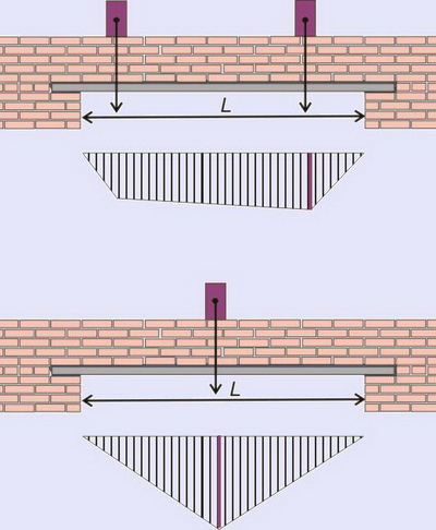
Below the beam arrangement diagram is a diagram of the bending moment acting on the beam, in our case the lintel. If the floor beams do not fall on the lintel, then the load from the floor beams is not taken into account at all in the calculation. As can be seen from the above diagrams, the maximum bending moment will act on the lintel if the floor beam is located in the middle:
M max = (Q x l) / 4
And the value of the load Q from the floor beam will depend on the distance between the floor beams.
For an opening 1.5 m long for a brick wall with a ceiling over beams 6 m long, with a distance between beams of 1 m, the load Q = 800 x 0.5 x 6 = 2400 kg
2. Selection of section.
2.1.1 The maximum bending moment for a non-cantilever beam on hinged supports, and in our case, a lintel, which is subject to a distributed load (in particular, a floor slab), will be in the middle of the beam:
M max = (q x l 2) / 8
2.1.2 The maximum bending moment for a lintel, which is subject to both distributed (the weight of the masonry, finishing materials and the lintel itself) and concentrated load (floor beams), will also be in the middle of the beam, but the moment is calculated using a different formula:
M max = (q x l 2) / 8 + (Q x l) / 4
Note: if the ends of the profiles rest on the partitions by more than 300 mm, then the beam can be considered not as lying on two supports, but as pinched on both sides, in this case the maximum bending moment will be on the supports: M max = (q x l 2) / 12, and the bending moment from the concentrated load M max = (Q x l) / 8.
For an opening 1.5 m long for a brick wall with floor slabs
M max = (3167 x 1.5 2) / 8 = 890.7 kg m.
For an opening 1.5 m long for a brick wall with floor beams
M max = (755.3 x 1.1 x 1.5 2) / 8 + (2400 x 1.5)/4 = 233.7 + 900 = 1133.7 kg m
2.2 Required moment of resistance:
W required = M max / R y
Where,
Ry- design resistance of steel. Ry = 2100 kgf/cm² (210 MPa)
Note: In fact, the calculated resistance depends on the strength class of the steel and can reach a value of 4400, but it is better to take 2100 as the most common. If two metal profiles are used for the jumper, then the value W required you need to divide by 2, if there are 3 profiles, then divide by 3 and so on.
W required = (890.7 x 100) / (2100 x 2) = 21.21 cm 3
For a 1.5 m long opening for a brick wall with a lintel of 2 profiles
W required = (1133.7 x 100) / (2100 x 2) = 27.0 cm 3
2.4. Well, now everything is simple, first we decide on the type of profile. The jumper can be made from hot-rolled steel angles, equal or unequal flange, I-beam channels, profile pipes. If, for example, the jumper is made from corners, open the corresponding assortment and see that the value of the moment of resistance is greater than that obtained in the calculation. The main thing here is not to confuse the axes about which the bending moment acts. In assortments, these axes may be called differently. Here the axis relative to which compressive and tensile stresses arise in the cross section is designated as z, in assortments this axis can be designated as X. But what is important is not the name, but the principle: when we determined the maximum bending moment acting on the cross section of the beam, then the length of the beam l measured along the axis X, height of the beam along the axis at, and the width of the beam along the axis z. Thus, no matter what assortment you take, and no matter what the axis is called, the main thing is that the width of the beam is determined along this axis.
For an opening 1.5 m long for a brick wall 2 bricks thick, 2 unequal corners 110 x 70 x 8 mm are sufficient(according to the assortment for such corners W z = 23.22 cm 3), or 2 channels No. 8P (according to the assortment for such channels W z = 22.5 cm 3)
For an opening 1.5 m long for a brick wall 2 bricks thick, 2 unequal corners 125 x 80 x 8 mm are sufficient(according to the assortment for such angles W z = 30.26 cm 3), or 2 channels No. 10P (according to the assortment for such channels W z = 34.9 cm 3)
Well, then everything depends on the availability of such a profile and the ease of working with it; if such profiles are not available for sale, or it is inconvenient to work with them, then any other profile with a large cross-section is accepted. In addition, for design reasons, instead of 2 corners, it is more convenient to use 4 corners, so that later it will be more convenient to operate brickwork. For example, instead of 2 corners 110x70x8, you can use 4 corners 90x56x5.5.
Note: The shorter the distance from the slabs or floor beams to the lintel, the more uneven the distribution of the load on the lintel will be. In this regard, it is recommended to take the profile cross-section by 5-20% larger. In addition, profiles of asymmetrical cross-section (unequal and equal-flange corners) are recommended to be connected with metal strips to increase the stability of the corners.
Metal lintels should be supported on the walls by at least 250 mm, and in earthquake-prone areas by at least 400-500 mm.
After selecting the section based on the maximum bending moment, it is advisable to calculate the deflection of the beam; there is even a special formula for this:
f = (5 x q x L 4) / (384 x E x I z)
Where,
q- load on the jumper defined in clause 1
L- opening width
E- modulus of elasticity, for steel E= 2 x 10 5 MPa or 2 x 10 10 kg/m²
Iz- moment of inertia according to the assortment for the selected profile, multiplied by 10 -8 to convert to meters (for 2 profiles this value is logically multiplied by 2), the main thing here is not to make a mistake with the axis.
For a lintel of 2 corners 110 x 70 x 8 mm above the opening 1.5 m deflection
f = (5 x 3167 x 1.5 4) / (384 x 2 x 10 10 x 2 x 171.54 x 10 -8) = 0.003045 m or 0.3 cm
For a lintel made of 2 8P channels above the opening, a deflection of 1.5 m
f = (5 x 3167 x 1.5 4) / (384 x 2 x 10 10 x 2 x 89.8 x 10 -8) = 0.0058 m or 0.58 cm
According to the requirements of SNiP 2.01.07-85* “Loads and Impacts,” the maximum deflection value for lintels should not exceed 1/200 of the span, i.e. in our case, the deflection should be no more than 150/200 = 0.75 cm. We have met this condition. If such a deflection of the lintel still does not satisfy you, then you need to select metal profiles of a larger cross-section. That's basically all.
Note: if the calculation was carried out under the action of a distributed and concentrated load, then it is more convenient to calculate the deflection separately for a distributed and concentrated load, and then add the resulting values.
 B1 in English what level?
 Managing verbs in German - German online - Start Deutsch
 Conjugation of the verb haben (to have) in the present tense